The Digital Communications Revolution: What is To be Done?
* Author: Ben Broughton
* Date: 2004-10-27
Contents
Goal List
- Optical fibre to the home available in 90% of households in the UK by 2020.
Details
- Begin deployment of fibre to the home in 100% of “greenfield” sites with no legacy architecture by 2006.
- Replace all twisted copper pair and hybrid fibre-coax connections from the home with optical fibre by 2020.
- In rural areas provide wireless connectivity to a fibre-node allowing the maximum data rate to households where a piped connection is impractical.
Analysis
There is still a great deal of debate within the telecommunications community as to the future of the industry, which data transfer mechanisms will predominate, and how far optical fibre will penetrate from the long haul backbone of the system to the ultimate end point at the customers household. Since the slump in the telecoms industry at the turn of the century, people’s expectations of the “insatiable demand for bandwidth” and the consequent hurried deployment of fibre to the home to supply it, have had to be drastically revised, causing a massive correction in the market value of telecoms related companies. The ability to send relatively large amounts of digital data along the existing copper-based telephone systems of most developed countries, and the emergence of wireless technology, means that an end-to-end optical communication network may not be necessary, or even commercially viable, for decades. The sudden point of this realisation can be seen in the share prices of telecoms companies, such as the leading optical components manufacturer JDS Uniphase. Massively overvalued at over $100 billion in 2000, the telecoms slump brought this suddenly to $5 billion where it has remained since.
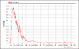
Figure 1: JDS Uniphase share price.
From an idealistic point of view, however, with regard to providing a communications network for the 21st century and beyond, the only answer to the question “what is to be done?” is to lay fibre to the home, and the sooner the better. This is because optical fibre far outstrips any other medium for transporting large volumes of data quickly and cheaply over long distances. If we are to realise an age where we have unlimited access to information and all our communications services come to us through a single port built into the home, fibre is the only option.
The existing twisted copper pair technology which provides most people today with their phone line and broadband internet via digital subscriber line (DSL) technology, is capable of transferring up to approximately 8 million bits per second (Mb/s) of information between peoples houses and the telephone company’s local exchange. With optical fibre delivering information to a specific neighbourhood, and coaxial cable covering the final section to the house, as in most cable television infrastructures, 50 Mb/s is achievable. This is a great deal of information capacity, approximately a feature length DVD in 10 minutes, and the anticipated limit for information carrying without the need to replace existing architecture and lay fibre to every home is an even larger 100Mb/s [[#1#]]. This is likely to be able to provide for consumer demand for years to come, but will not be enough to facilitate the dream of hundreds of digital television channels, video on demand, virtual commuting and massive information sharing ability, all through one port. A single fibre optic cable is capable of carrying information at over 100 gigabits per second on a single wavelength channel, and with multiple wavelength channels transmitting simultaneously down a single fibre (known as dense wavelength division multiplexing, DWDM), the perceived limit is in the tens of terabits per second, enough to carry all of North America’s data traffic several times over, down a single fibre. It is reasonable to assume that this is more information capacity than anyone will ever need in the foreseeable future.
The majority of the journey any information is sent on over a long distance today is already via optical fibre, as fibre’s huge information capacity and ability to allow propagation over long distances with minimal signal loss made it instantly worthwhile to replace the copper submarine cables between continents, and national trunk cables with fibre. Even communication networks on the citywide or “metro” level are in the process of being converted to all optical, although the layout of the actual implementation will depend on the cost of components such as optical amplifiers to boost the signal. It is only therefore the “last mile” between the telecoms company’s local exchange and the customer’s home which is likely to remain non-optical. So if we have the ability to future-proof our homes indefinitely for connectivity, dispensing with the traditional phone, TV aerial, satellite dish, VCR/DVD recorder and internet connection at once, merely by completing the last segment of an already optical network, the technology for which already exists, why is it not happening?
The reason is a combination of two factors:
- Lack of consumer demand for increased bandwidth, meaning that the existing copper architecture will suffice for some time to come.
- The initial expense of literally digging the old cable out of the ground and replacing it with fibre, and also installing the optical components which are not cheap into millions of homes.
The potential revenue from increased consumer demand will keep rising however, albeit much slower than previously thought, and the cost of optical components should fall with further developments and suitability for mass production, so it is a matter of waiting until the former is able to offset the latter. The popularity of the internet is still growing tremendously, with the number of estimated users now at 800 million [[#2#]], having approximately doubled each year through the late nineties. What is important from a telecoms perspective, though, is the total amount of traffic these users are generating. Internet traffic overtook voice traffic on the backbones somewhere in 2000-2001, and now dwarfs it. As the plot in figure 2 shows, the internet traffic on the U.S. long-haul backbone has increased faster than the number of users, suggesting that as bandwidth becomes cheaper, each user creates more traffic individually, as well as encouraging new users.
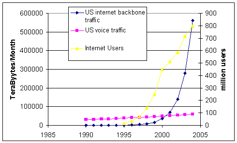
Figure 2: Estimated US internet backbone traffic in and voice traffic in TB/Month, with the total number of internet users in millions. Data from [[#3#]] and [[#4#]].
The fall in the cost of bandwidth has been phenomenal. Today, a 1Mb/s, always-on “broadband” connection is available to most UK homes with no monthly download limit for £30/month. 5 years ago, to get an equivalent amount of data to the home with a standard 56kb/s phone modem, even at 1 pence per minute off-peak rate, would have cost approximately £8000, and would have required 18 phone lines. This is an exaggerated example from the end of network cost, but even the cost for high bandwidth (>500Mb/s) has dropped from $750 to $50/Mb/s/month in the last 6 years [[#2#]]. It seems that however much bandwidth can be supplied to the customer for less than around $50 per month will be readily soaked up, and services operating on this level of bandwidth will flourish, but this still leaves the chicken-and-egg problem whereby large bandwidth will not become genuinely cheap until there is large-scale take up, and that take up will not occur until bandwidth is widely available very cheaply.
Aside from the indefinite wait for the market to catch up with the technology available, this disparity between cost and potential revenue can only be resolved if:
- Component prices plummet. This will speed up the conversion of the metro level networks to optical architecture, bringing fibre a step closer to the home, and bringing much greater bandwidth below the $50 threshold. Development of all optical switches and routers will remove the need for electronic exchanges, again reducing costs greatly, but still demand would have to increase beyond the capability of copper in order to make the civil engineering worthwhile bringing fibre to the home.
- There is an emergence of a “killer application”, which requires huge bandwidth and is so appealing consumers would feel they can no longer live without it, and would be willing to pay enough for it to offset the costs of cable replacement.
- Several governments decide that the potential benefits of a truly interconnected society justify the costs of a publicly funded overhaul of the copper network and replacement with fibre.
Components suppliers are working constantly to reduce the cost of the key devices needed for a fully point-to point optical network such as signal routers, switches and amplifiers in the hope that the viability crossover point can be brought forward.
The problem is that, for long-haul networks where fibre optics have been so successful, it is the electronic signal regeneration “repeater stations” that produce most of the cost. As these are trunk routes, there are very few network nodes, so very few optical switching and routing components are required. It is therefore device performance that is crucial, as the better the optical components perform, the greater the distances between repeaters can be, so cost is reduced overall. As the optical network progresses to the metro level, however, transmission distances are greatly reduced, so component performance is no longer crucial, but the number of network nodes increases dramatically, so components are required in much greater number and cost, rather than performance, becomes the key factor. This problem is magnified still when fibre to the home is considered, as every single household will need an optical transceiver, which will have to be cheap enough to be “given” away to new subscribers, in the manner of a Sky digibox, in order to guarantee take up. As well as cost reduction, new devices are sought which can perform the required functions all-optically, for the same reasons as with long distance repeater stations, anything which saves the optical signal from being converted to electronic and back again saves money. This progress, however will take time, and will still rely on there being sufficient increased demand for the technology on completion that it is worth the copper replacement costs. As long as 15 years ago, components manufacturers were designing optical transceivers to receive data at 622Mb/s and transmit at 155Mb/s, to be manufactured for $40. This is over 500 times the bandwidth of today’s standard broadband connection, yet has still not been realised due to lack of demand. For a more in-depth look at the technology of optical communication systems and network components, please see the “technology” appendix.
As for a killer application, none has emerged so far. Voice over internet protocol (VoIP) has been touted as a huge benefit of switching to an all digital connection as the cost of long distance calls could be greatly reduced, and video could be transmitted simultaneously. This has its problems though, in that IP data is transmitted in packets which can be routed separately. This has the benefit that no dedicated line for the call is required, so long-distance connections are made much cheaper, and is fine for data, but for a conversation the information needs to arrive in a constant stream which makes a dedicated connection preferable. Also the plain old telephone system (POTS) as it is referred to powers itself, allowing emergency communication in a black out, which would shut down an internet connection. Nevertheless, BT is to trial VoIP in Cambridge and Woolwich before an envisaged conversion of its whole system to the so called 21st century network (21CN) in 2008. Voice alone though, is not bandwidth hungry enough to kick-start copper replacement. As for video phones, people are generally lukewarm to the idea, and certainly do not seem willing to pay significantly extra for it. Other high bandwidth applications such as customised television or video on demand, picture/video sharing and high bandwidth network gaming, are all either partially available over copper or satellite, or do not excite the public enough to generate serious demand.
One feature of their communication service people are willing to pay for is mobility. People routinely spend £30 to £50 per month on their mobile phone, and the introduction of a comprehensive fibre network could reduce this drastically. If most houses had a fibre connection, with vastly more bandwidth than they ever use, connected to a wireless node, their mobile phone call, and even those of passers by within range could be routed down the fibre at virtually no cost. Every house and building would effectively become a low power mobile antenna, reducing costs and negating the need for unpopular high-power masts. This could even reduce the health risk of mobile phones, with intelligent handsets detecting nearby nodes and cutting their power output accordingly.
Interestingly, the one static application which did appear to be both bandwidth-hungry and popular enough to generate serious demand was peer-to-peer file sharing of music, e.g. Napster. The illegality of this activity however has prevented it from providing the desired broadband kick-start. It has been suggested, somewhat tongue-in-cheek, that as the telecoms industry is worth roughly 20 times that of the recorded music industry, the telecoms companies should buy the record companies and make music free on the internet, but this radical a step is obviously unlikely [[#2#]].
This then leaves us with government intervention. Since the major telecoms companies such as BT are no longer government owned an outright overhaul is very unlikely. In the U.S, however, there is some political pressure to provide public subsidies and tax credits to companies rolling-out fibre, in particular to rural communities which stand to benefit the most having no cable access, and bills have been drawn up to this effect [[#5#]]. The only probable government related outcome would be pressure on developers to install fibre optic cable to the home in “greenfield” sites where there is no previous network of any kind.
In Europe, particularly Scandinavia, and some states of the US, “fibre communities” are being trialled, in which new-build housing developments are fitted with fibre to the home. This makes sense as, when building from scratch, installing fibre is only marginally costlier than installing copper for the first time, and actually cheaper than hybrid fire/coax. With falling fibre component prices, installation costs per home have now been estimated at $2057 and $2720 for fibre and coax, respectively [[#6#]]. Having the fibre in place also effectively future proofs the houses, as any changes in transmission speeds or protocols can be effected by simply changing the transceiver devices on the end-points of the fibre. This is exactly what was seen in the existing long-haul systems with the introduction of DWDM; the capacity of the fibre links between continents was multiplied simply by attaching improved transceivers at each end capable of transmitting several wavelength channels simultaneously down the same fibre. It seems the best hope at the moment is for these trials to prove extremely popular and spark an overall increase in demand.
In the UK in particular, there is a huge opportunity for this kind of trial due to the massive house-building proposals announced for the south-east. With as many as 200,000 homes planned for the next ten years, if the government takes the opportunity to enforce fibre laying to the home in all of these developments, that would provide a large enough user base “chicken” for several profitable new service “eggs”, which could then expand and spark take-up elsewhere. This is an action for which the telecommunications companies and the public in general ought to be lobbying hard. Legislation to prevent the wasteful installation of copper in brand-new developments could provide the required “kick start” for more widespread fibre roll-out.
It should be said at this point that the Far East is well ahead on fibre deployment, where in Japan in particular, fibre has been laid in much more quantity on the assumption that they will one day need it. This is a much more forward thinking approach, and consequently the completion of an all-optical network will require much less future investment there. Having the fibre in the ground already is a huge advantage, as this represents a large portion of the cost, and despite uncertainty in the final specifications of the network, all that will require changing is the transceivers at the ends of the fibre to bring the system up to date. Perhaps if an all-optical network can be established in Japan the benefits will become apparent, and demand will appear in the West. Until then, we are in the slightly unsatisfactory situation of having the capacity of copper cabling gradually improved to match gradually increasing demand, when all the while we have the technology available to effect a step-change in the level of our interconnectivity.
Technology
Fibre Systems
In order to discuss current optical network components and their applications, a short introduction to the basics of fibre optics is required. An overall network architecture for a telecoms network is shown in figure 3. As can be seen it consists of a series of ring networks at three levels, the long-haul, the metro and the access level. As discussed above, the long-haul rings are all optical fibre operating dense wavelength division multiplexing systems for maximum information carrying capacity with minimal loss over distance. The metro rings are in the process of being converted to all-optical transmission, and will probably end up running DWDM. The final layout of optical metro networks will depend on how the demand for bandwidth increases from now, and how cheap optical components become. The access level network meanwhile remains electrical, with coax and twisted copper wiring running from most homes and businesses to their local exchange. Any given connection therefore will originate at the access level, cross several nodes where it is redirected on its way onto the long haul backbone, then several more switching points on its way off the backbone, through the metro level to the destination.
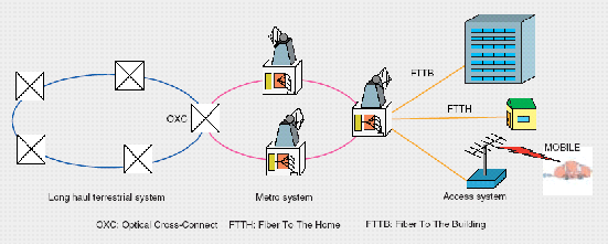
Figure 3: A generic telecommunications network diagram.
An example of the hardware any given signal has to traverse on its way from point-to-point is shown in figure 4. The light signal is generated at very specific wavelength by a monochromatic semiconductor diode laser, such as a distributed feedback laser (DFB) [[#7#]]. The light output from this laser is switched on-and off very rapidly to impress upon it the desired signal for transmission. This signal, consisting of a series of very short light pulses is then fed into an optical fibre and starts its journey.
Immediately it will be joined in the fibre at the multiplexer by a host of other signals, each carrying completely different information and consisting of light pulses which are of a very slightly different wavelength (colour). Each of the wavelength signals is then switched in a series of cross-connects to direct them to the correct destination, whereupon the individual wavelengths are singled out by the add-drop multiplexer and detected by a photodiode receiver. In order for the signal to arrive successfully, the light pulses must still be of sufficient intensity to be distinguished from the spaces between pulses, and must have not merged into one another to the point where they cannot be distinguished form one another. The two processes causing these effects are known as attenuation and dispersion respectively, and must be minimised in a communication system.
Attenuation is loss of light from the fibre, caused by light either escaping from the fibre or being absorbed by impurities in the fibre. Light in an optical fibre is confined in a glass core which is surrounded by glass cladding of lower refractive index than the core. This causes the light to undergo total internal reflection at the core-cladding interface and channels it down the core, in exactly the same manner as observed in a stream of water by John Tindall in 1870. Light is then lost from the fibre only if the light strikes a defect in the core-cladding interface, is scattered or absorbed by impurities in the fibre, is absorbed by the silica glass or if the fibre is bent beyond the minimum radius of curvature for transmission. As modern fibres are virtually defect free and manufactured to tremendous purity, losses are very low and are governed by the fundamental limits of Rayleigh scattering which decreases with increasing wavelength, and silica absorption, which increases with wavelength. Figure 4 shows the wavelength dependent loss in silica fibre, and the “transmission windows” between the areas of high scattering and high absorption at 1300 and 1550nm.
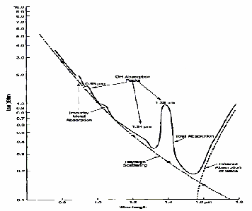
Figure 4: The spectral absorption for silica fibre.
As the figure shows, losses in the transmission windows are exceedingly low, down to about 0.2dB/km, meaning only 5% of the light is lost in each km of fibre. This loss, though small, is unavoidable, and must be compensated for by periodically boosting the signal. This is done using erbium doped fibre amplifier (EDFA) devices which use a laser coupled into the transmission fibre, but emitting at a shorter wavelength than the signal light, to excite erbium impurity atoms which are doped into a small section of the transmission fibre. As the signal then passes through this energised section of fibre, stimulated emission occurs and the signal is amplified on a photon by photon basis. This eliminates the need for electronic amplification of the signal.
One disadvantage of non-electronic signal amplification, though, is that dispersion cannot be corrected at the same time. Dispersion is the spreading out of the light pulses in time as propagate. There are several sources of dispersion in fibres.
Modal dispersion can be considered as the light rays taking different paths down the fibre. A ray which bounces back and fore across the fibre many times on its way effectively travels a longer distance than a ray which goes straight down the middle, and so takes longer. This type of dispersion is eliminated by the use of single mode fibre, which utilises an especially narrow core (<10µm), to allow only light which travels straight down the fibre. Figure 5 shows the simplified differences in propagation in multimode and single mode fibres.
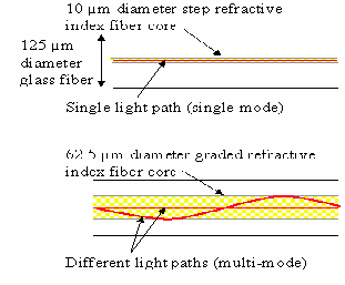
Figure 5: Propagation in single mode and multimode fibre.
Chromatic, or material, dispersion is a result of the refractive index of the glass varying with wavelength. All light signals have a finite spectral width, so a pulse which is made up of light with a small spread of wavelengths will therefore separate as it travels. Shorter wavelength portions of the pulse will either lag or lead the longer wavelength sections, causing the pulse to merge into the space for neighbouring pulses. This is illustrated in figure 6. This can be reduced however by the use of chromatic dispersion compensators and dispersion shifted fibre, so is no longer a problem in current transmission systems. It may become a more significant problem though as systems move to higher data rates and more closely packed wavelength channels.

Figure 6: An illustration of chromatic dispersion.
Polarisation mode dispersion (PMD) is the smallest dispersion effect in optical fibres, and is insignificant at current 10Gb/s data rates, but as 40 Gb/s and above rates become adopted, it will become a serious concern. PMD results from non-uniformities in the density of the fibre caused by bending stresses, temperature gradients and vibrations the fibre may be subject to. This causes light which is polarised in one direction, say vertically in the fibre, to travel slower then light polarised orthogonally to this. A light pulse which has components in both these directions (i.e. polarised in a direction between horizontal and vertical) will then experience two different refractive indices and will broaden as it propagates, eventually merging with neighbouring pulses and making the signal unreadable.
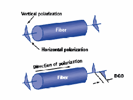
Figure 7: Polarisation mode dispersion illustration
As PMD is a result of variable environmental factors, not a fundamental property of the fibre as with modal and chromatic dispersion, the amount of pulse spreading, known as differential group delay (DGD) is constantly varying in a transmission system, so active polarization control devices are required to compensate for it. This is an ongoing area of research.
Network Components
As the above outline has hopefully shown, the technology for optical communications is well established, it is mainly economic considerations which are holding back the uptake of optical systems in the metro and access levels of telecommunications systems. For this reason, most current technological research efforts are concentrating on developing components to reduce the cost of optical systems. This means cheaper equivalents of currently deployed devices, such as optical amplifiers, and new devices which can remove the need to convert the optical signal to an electronic one to perform some function, such as routing, before re-transmitting optically, thereby removing the cost that this incurs. The principal devices which current research is aiming to develop are therefore: improved cheaper EDFAs, optical add-drop multiplexers, PMD compensators and particularly all-optical cross connects.
Optical cross-connects are devices which can direct light from any one of a number of input fibre to any one of a number of output fibres, this allows the signal to be routed along the desired path. In current networks this function is performed electronically, although all-optical versions are now commercially available. Current devices are based on micro electro-mechanical systems (MEMS) which consist of hundreds of tiny tilting mirrors which are electrically switched to deflect the light one way or another. MEMS switches are effective, but relatively slow, taking milliseconds to switch, and also suffer from scalability problems as the hundreds of mirrors required to make large port count devices require very complex software to drive them.
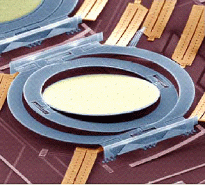
Figure 8: Microscope image of 2-axis MEMS mirror [[#14#]]
Other technologies for this application include liquid crystal beam steerers, which use switchable holograms to route light from an input fibre to anyone of up to a thousand output fibres. In such a device an LCD display is used to generate a phase hologram (one in which the light is only slowed down in certain areas, rather than blocked), the image from which is a bright dot formed at the end of the desired output fibre. These have the advantage of being fast and scalable with no moving parts, but generally have higher losses and require further development to improve their diffraction efficiency [[#15#]].
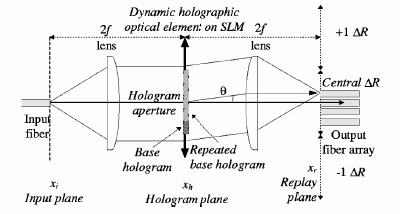
Figure 9: Schematic of a holographic liquid crystal beam steerer.
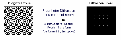
Figure 10: Illustration of LCD hologram pattern and consequent output image.
PMD compensators are devices which are capable of receiving light which is varying in its state of polarisation (SOP), and correcting this to produce a constant output polarisation, i.e. removing any differential group delay in a reversal of the process shown in figure 7, by slowing down the light polarised in the direction which travels faster in the fibre.
A device which slows down light polarised one direction relative to light polarised orthogonally is know as a waveplate (one which introduces a delay of half a wavelength is known as a half waveplate). A series of three optical waveplates, which can each be rotated to adjust the direction of polarisation they affect, is capable of correcting any input polarisation state. If these are controlled automatically as part of a feedback loop, the system can be auto-rotated to constantly correct for the desired output despite a randomly fluctuating input SOP.
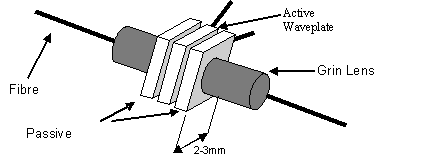
Figure 11: Layout of rotatable waveplate in fibre system for PMD compensation.
Mechanically rotatable waveplates, and those based on mechanical fibre squeezers, have been tested for this application, but more elegant solutions are being researched in which the waveplates consist of electro-optic materials in which the optic axis direction of the waveplate is determined simply by the direction of the electric field. An arrangement of radial electrodes therefore allows endless rotation of the optic axis with no moving parts and much quicker response times than any mechanical device. Electro-optic materials which have been examined for this type of device include lithium niobate [[#16#]], liquid crystals [[#17#]] and electro-optic ceramics [[#18#]]. Each of these has their own advantages in terms of response time, power consumption and optical rotation power.
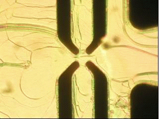
Figure 12: Polarizing Microscope image of a liquid crystal rotatable waveplate.
It is hoped that the development of fast, reliable PMD compensators will allow cheaper upgrades of current networks from 10GB/s to 40GB/s per channel.
Gain Flattening in EDFAs and wavelength selection for multiplexing and de-multiplexing are the remaining application undergoing development. Gain flattening is required in DWDM systems as the EDFA amplifier may not amplify all the wavelength channels equally. This can lead to distortions in the signal, so selective wavelengths have to be partially filtered out or attenuated. Wavelength multiplexing requires that very fine wavelength regions be selectively reflected or transmitted through the multiplexer. One device which is capable of gain flattening and wavelength selection is a fibre Bragg grating.
fig. 13
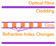
Figure 13: Fibre Bragg Grating Diagram [[#11#]].
The fibre Bragg grating is a section of fibre in which the glass of the core is chemically altered by UV exposure to create a periodically varying refractive index. Light with a wavelength exactly matching the periodicity of the index variation will be totally reflected due to constructive interference of the small reflections from each refractive index change (Bragg reflection) and can therefore be tapped off. The remaining wavelength channels will be transmitted. This allows very specific multiplexing of closely spaced wavelengths. Wavelengths very close to the reflection wavelength will experience partial reflection, allowing gain flattening also. Current challenges include making fibre gratings wavelength tunable and improving their wavelength selection characteristics. Other methodologies for multiplexing and gain flattening include arrayed waveguide gratings, which split a fraction of all the multiple wavelengths in a fibre and interfere them with themselves upon recombination in order to separate them into different fibres, and polymerised liquid crystal variable attenuators.
While this hopefully has given an insight into the types of optical component being developed and how they will fit into the desired goal of an all-optical super high bandwidth communications network, it must be remembered that the perceived final network topology is still far from certain. While the economic situation and rate at which investment returns to the telecoms industry will be crucial in the type of network that finally gets deployed, so will the future development of components. Which components emerge as being able to perform certain tasks in the cheapest, most effective, most reliable manner will determine how much functionality is built into the network, which type of layout it adopts, and even which sort of protocol is used to carry the information (e.g. telecoms standards such as ATM or Ethernet). For further insight into recent developments and the online debate between experts and interested lay-people alike, please view the industry forums in [[#11#]] and [[#12#]].
Bibliography and References
- [1]
- [10]
- [11]
- [12]
- [13]
- [14]
- [15]
- [16]
- [17]
- [18]
- [2]
- [3]
- [4]
www.dtc.umn.edu/~odlyzko/misc/thierer-broadband-paradox
- [5] Solving the broadband paradox, Adam D. Thierer;
Issues in Science and Technology2002-4
- [7]
- [8]
- [9]